Easy-to-operate charge amplifier for converting electrical charge signals into proportional voltages.
Twelve ranges, calibrated in mechanical units per volt and adjustment of the transducer sensitivity.
Frequency range from quasistatic measurements up to 180 kHz. Three selectable time constants and plug-in fil ters for matching the frequency range to the measuring duty.
MEASURI NG WITHOUT MATHS
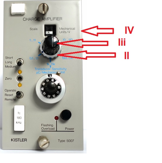
- Set the sequence of numbers of the transducer sensitivity on 10-turn potentiometer I in pC/M.U. (mechanical u nits, e.g. N, bar ,g etc.).
- Set range selector Il for transducer sensitivity to appropriate range.
- Select the scale (lii). Altogether 12 calibrateci scales are available, graded 1-2-5.
- In window IV the scale far the charge ampifier output voltage is displayed directly in M.U./V.
- lndicators, recorders and oscilloscopes connected to the voltage output are adjusted to 1 V/div or 1 V/cm. This means that the scale selected on the charge amplifier gives the display scale in M.U./div. or M.U./cm directly.
Example:
Force transducer with 4,00 pC/N sensitivity. A scale of 100 N/V is selected. Because the ampli fier can be driven to ±10 V, the measuring range is now -1 ... +1 k N.

DESCRIPTION
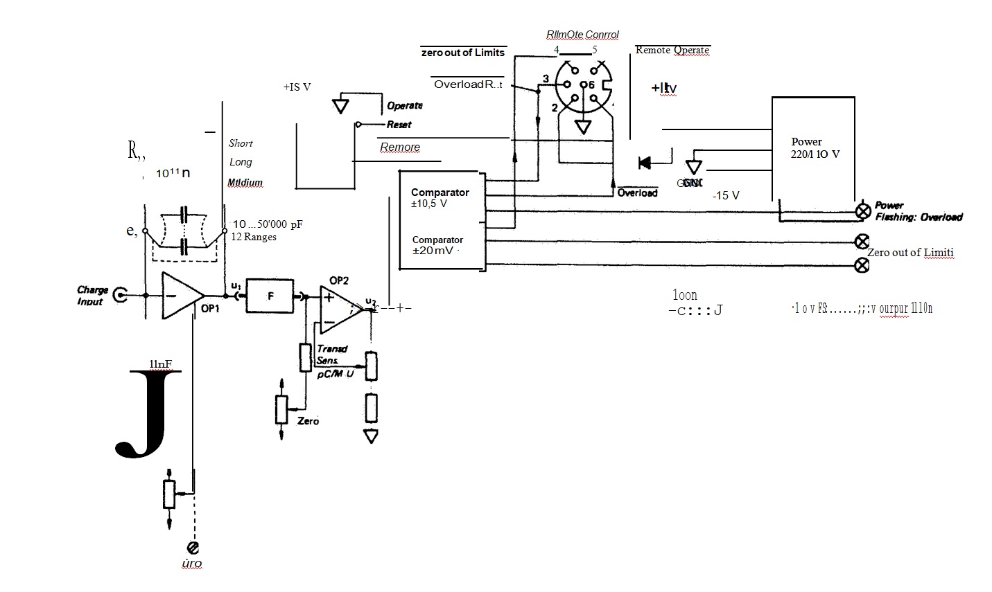
The charge amplifier consists essentially of an operational amplifier OP1 with high input impe dance and high open loop gain, and a highly insulating feedback capacitor C9
The input impe dance of this feedback amplifier circuit is thus virtually nil. However the high insulation resistance at the input is retained, because theinput stage is equipped with a double MOSFET. Through the capacitive feedback the charge amplifier generates a charge Q = U • C9 , which is equal with reverse sign to that delivered by the connected transducer.
The charge yielded by the transducer thus appears to pass straight onto the feedback (range) capacitor Cg. Consequently the resulting output voltage U = Q/C9 is proportional to the charge and hence also to the measurand acting on the transducer. The voltage at the input remains so low that the cable capacitance has virtually no effect on the measured result.
The feedback capacitor may be short-circuited with a reed relay (Reset} paralleling it, thereby fixing the measuring zero for quasistatic measurements ( Long time constanti). This relay is either operateci by the Reset switch or remote controlled. By switching-in optionally either a 100 Gn or a 1 Gn resister R 9 paralleling the feed back capacitor, the time constant (Medium or Short time constant) is shortened, allowing dy namic measurement without drift.
While the lower cutoff frequency is given by the time constant R9 • C9 ,the upper cutotf frequency can be selected within a wide range by means of a plug-in low-pass filter F {standard: 180 kHz).
An Overload display signals and records any overdrive of amplifier OP2 {output voltage outside the range -10,5 ... + 10,5 V). At thesame time a corresponding logie signal appears on the Remote Control connector. This display is cleared with the Reset switch or remote controlled.
With closed reed relay { Reset position), two LEDs Zero indicate any zero drift in the charge amplifier. Far exacting measurements this can be corrected with a screwdriver.

OUASISTATIC MEASURING
Despite the prejudiced opinion often expressed, it is possible to measure not only dynamically but also quasi statically with piezoelectric trans ducers having a quartz transducer element. This is done with the Long time constant setting. Maximum measuring duration depends essentially on the strenght of the transducer signal and the acceptable error. Such measurements presuppose adequate insulation resistance of more than 1 T.n in the input circuit (transducer and cable). Rapid temperature changes at the transducer must also be avoided.
Far a rough estimate of the possible measuring duration it is sufficient to compare the charge signal (pC) delivered by the transducer with the maximum drift (0,03 pC/s) specified for the amplifier. More detailed information about this is given in the operating instructions.
By appropriate operation of the Reset relay, in many cases it is possible to eliminate the d rift periodically, so that measuring duties can be performed which were previously amenable only to true static measuring systems.
FREOUENCY RESPONSE
The amplifier is equipped with a low-pass filter which may be plugged into the front pane!. Type 5311 with a cutoff frequency of 180 kHz is supplied as standard filter. As alternatives, filters may be had with cutoff frequencies down to 1O Hz, see data sheet 12.011. The filters have a Butterworth characteristic with a very flat f re quency response and a steep drop of 12 dB/ octave above the cutoff frequency.
The low-pass filters are employed generally to eliminate oscillations and pulses of higher frequency superimposed upon the actual measured variable. This is the case tor example when a quasi static measurement is disturbed by an additional high-frequency signal due to structure bome noise.


![]() KISTLER - 5007 Charge Amplifier
KISTLER - 5007 Charge Amplifier