|
|
|
|
|
| Donate | App | Join | Log in |
|
|
|
|
|
| Donate | App | Join | Log in |

- AI Artificial intelligence
- App
- Artificial intelligence AI Video generators
- Computer - Cell phone
- Electronic Brand
- Electronic Flea Market
- GPS - GPRS
- HAM Radio
- I.C. & functions
- Instruments
- Instruments - Funcions
- Internet
- LAN
- Optics
- Phones
- Photography
- Software
- Solar panels
- Tablet
- Tracking
- Video - TV
- Weather Stations
- Web - Best sites
![]() SDRangel ADS-B installation, problems and solutions
SDRangel ADS-B installation, problems and solutions
Rating : 9
| Evaluation | N. Experts | Evaluation | N. Experts |
|---|---|---|---|
| 1 | 6 | ||
| 2 | 7 | ||
| 3 | 8 | ||
| 4 | 9 | ||
| 5 | 10 |
0 pts from Al222
| Sign up to vote this object, vote his reviews and to contribute to Tiiips.Evaluate | Where is this found? |
 | "Descrizione" about SDRangel ADS-B installation, problems and solutions by Al222 (20707 pt) | 2025-Jan-25 11:01 |
| Read the full Tiiip | (Send your comment) |
SDRangel ADS-B installation, problems and solutions
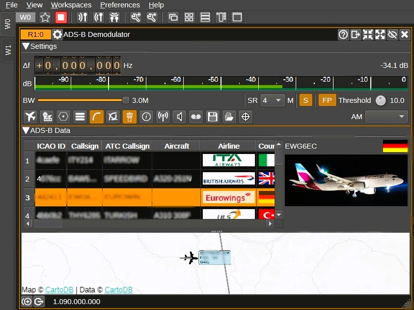
To demodulate the ADS-B signals that are transmitted from aircraft to ground stations and used to communicate flight data, the SDRangel program has a dedicated plugin called ADS-B Demodulator.

SDRangel is an open-source platform for managing Software-Defined Radio (SDR). It enables the transmission, reception, and analysis of radio signals using SDR devices such as RTL-SDR, HackRF, LimeSDR, and others.

Key Features:
- Multi-mode support: Handles a wide range of radio modes, including FM, AM, SSB, DMR, P25, ADS-B, AIS, and more.
- Advanced graphical interface: Provides visual tools for configuring, decoding, and analyzing signals in real-time.
- Cross-platform compatibility: Works on operating systems like Windows, Linux, and macOS.
- Extensibility: Built on a modular architecture, allowing plugins to add new features and modes.
Main Applications:
- Amateur radio
- Communication monitoring
- Research and development of RF applications
- Decoding digital signals such as DMR, AIS, ADS-B, RTTY, Morse etc.
Download SDRangel x Windows: Releases · f4exb/sdrangel
Support: Issues · f4exb/sdrangel · GitHub
Forum: SDRangel - Index page

Run the downloaded.exe
Two windows are opened:
 |  |
For the time being, close Configuration and leave SDRangel open.
Let us see what are the input devices through which SDRangel is able to decode the signals and we set up the RTL-SDR key.
Click in the upper left corner on the Add Rx device icon

and then on the popup arrow

______________________
Now I list some problems that may occur at this point of the installation and their solutions.
- Problem. The RTL-SDR dongle does not appear in the list above, that is, you do not see RTL-SDR....
- Solution: check if it is present in the "Safe Hardware Removal" icon at the bottom right of the monitor

If it appears there, it means that it has already been installed. SDRangel does not see it because it is already installed.
If the dongle RTL-SDR does not appear:
- or the dongle is not inserted into the USB socket
- or the dongle has not been installed with the Zadig program.
So it is essential to use the program Zadig
Download Zadig
Zadig - USB driver installation made easy

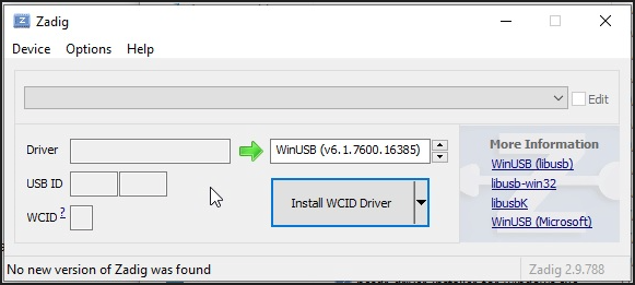
Zadig is a Windows application that installs generic USB drivers such as WinUSB, libusb-win32/libusb-1.0.dll, or libusbK, which are necessary for a wide range of USB devices to communicate with Windows. It is especially useful for RTL-SDR because standard drivers do not support this device. Download Zadig from the official website and launch the application.
Connect the RTL-SDR Device Before running Zadig, connect your RTL-SDR dongle to a USB port on your computer. This ensures that the device is ready and detected by Zadig.
Open Zadig and Select the RTL-SDR Device Once launched by clicking on Zadig.exe, Zadig should automatically detect the RTL-SDR dongle. Open the dropdown menu within the Zadig interface and select the device listed as "Bulk-In, Interface (Interface 0)" or a similar name. If the device does not appear in the list:
- Check your connections and make sure the dongle is properly inserted. If the device does not appear in the dropdown menu, proceed with the installation as long as "Install WCID Driver" is an option.
- If multiple dongles are present, repeat the process for each dongle.
Install the WinUSB Drivers With the device selected, proceed to install the WinUSB drivers by clicking on "Install Driver". This action will replace any existing drivers the dongle might be using with ones compatible with RTL-SDR operations. This step is crucial as it ensures that rtl1090 or any other SDR software can effectively communicate with the dongle.
If no device shows up on the screen, as mentioned above, select Options and then List all devices, choose the type of dongle, and click on Install WCID Driver.
Click Options>List All Devices

From the dropdown list, several devices might appear: any of them are generally fine, but ensure that "Bulk-In, Interface (Interface 0)" or "RTL2832UHIDIR" or "RTL2832U" or "Blog V4" is selected in the USB ID box, and that the selected dongle's USB ID is "0BDA 2838 00".
Make sure that "WinUSB" is displayed in the box indicated by the green arrow, while the box on the left is not important. Click on "Replace/Install Driver" This operation may take a few minutes, and during this time, you will see "Installing Driver" When "The driver was installed successfully" appears, click "Close" and close the Zadig window.

This procedure must be repeated if you add a new dongle or change the dongle.
The first operating screen, so the one that allows you to adjust frequency and signals should be this one, in the left part the Receiver and in the right part the Spectrum display.

- Problem. The Spectrum display does not appear or if you have closed it with the upper right button.
- Solution: You can make it reappear with the lower left button in the receiver window

____________________________
The ADS-B demodulator is activated by the receiver plugin with a click on the triangle icon

Choose the appropriate demodulator from the drop-down menu and then click on Apply. The demodulators, at the moment (January 2025) are well 40 to which we add the Features that we will see later. They are all listed in the drop-down menu that opens with a click on the triangle icon at the top left of the Receiver, but for convenience I report them aggregated.

ADS-B Demodulator
After selecting the ADS-B Demodulator, you need to:
- Set the frequency to 1.090,000.
- Click DC and IQ.
- Set the Sample Rate (SR) to 2,400,000.
- Select DEC at 1.
- Check the AGC box. AGC is useful, but it is not suitable for all types of reception.
AGC (Automatic Gain Control) is a feature used in electronic devices to automatically adjust the input signal level. It is widely employed in communication systems, radios, audio equipment, and SDR systems to optimize signal quality.
What it's for:
- Automatic adjustment: Keeps the signal level consistent by compensating for variations in intensity (e.g., signals that are too weak or too strong).
- Quality improvement: Reduces distortion and saturation, enhancing signal clarity and processing.
- Versatile applications: Used in radio receivers, microphones, recorders, and SDR systems.
- Adjust the volume. This adjustment depends a lot on the signal strength, the type of key, whether AGC is active or not, the type of antenna, the amplifier if any, the quality of the cables, possible disturbances etc. So it is not possible to give advice that is useful for everyone.

The best results can be achieved with an antenna amplifier in this configuration:

At this point, you just need to click on one of the two blue triangles in the top left-hand corner to make it work. Why are there two? Because if there are several receivers, each can be switched on separately with its own button or they can all be switched on at the same time with the topmost button.

(Attention: It is possible to receive different and separate frequencies on different receivers, but each receiver must have its own RTL-SDR dongle so for example, 2 frequencies, 2 RTL-SDR.).
- Problem. This error message may appear

and, if you click on the blue background triangle icon that is used to activate the receiver, you receive this other error message:
Could not start sample source

- Solution: Close the receiver window by clicking on the X in the top right-hand corner and reopen the window, checking that the "Sample rate" is higher than 2,000,000. In the image below it is 1,024,000. Increase it to 2,024,000

- Problem: The Receiver plugin (the one you see above) does not appear.
- Solution: In the menu on the top left, click on the 4° icon>Select sampling device>RTL-SDR(0)

Let's look at all the buttons present in the ADS-B Demodulator plugin and their functions.


Frequency Shift from Center Frequency of Reception Value
Adjust the frequency shift using wheels, measured in Hz from the center frequency of reception. Right-clicking on a digit will reset all digits to the right to zero, effectively rounding down the value at that digit's position. You can adjust the wheels using the mouse wheel or by clicking on a wheel and using the keyboard arrows. Holding the shift key while adjusting will change the value by increments of 5, and holding the control key will change it by increments of 2. Clicking directly on a digit will set the cursor to that digit.

Channel Power
Displays the average total power of the received signal within the passband, measured in dB relative to a +/-1.0 amplitude signal.

Level Meter in dB
- Top Bar (Green): Displays the average value.
- Bottom Bar (Blue-Green): Shows the instantaneous peak value.
- Tip Vertical Bar (Bright Green): Indicates the peak hold value.

RF Bandwidth
This indicates the bandwidth in MHz of the channel signal prior to demodulation.

SR - Channel Sample Rate
This setting determines the sample rate used by the demodulator, with supported values ranging from 2M to 12M samples per second (Sa/s), in increments of 2MSa/s. Ideally, this should match the baseband sample rate (the sample rate received from the radio). If there's a discrepancy between the baseband sample rate and the demodulator's sample rate, interpolation or decimation will occur to align them. Note that interpolation requires substantial processing power and might lead to dropped samples.
A setting of 2 MSa/s generally provides satisfactory decoding. You may try higher rates if your hardware supports it, but be aware that higher rates require more processing power.

S – Demodulate Mode-S Frames
Activating the 'S' button allows the demodulator to process Mode-S frames, including:
- ELS (Elementary Surveillance)
- EHS (Enhanced Surveillance)
- MRAR (Meteorological Routine Air Report)

FP – Full Preamble Correlation
If 'FP' is enabled, the demodulator will match the received signal against all 8 bits expected from the ES1090 preamble. If disabled, correlation will only occur on the first 6 bits. Limiting correlation to the first 6 bits can reduce processing load but may also increase the detection of invalid frames.

Threshold
Sets the correlation threshold (in dB) between the received signal and the expected 1090ES preamble. Lower threshold values allow more frames to be decoded, require more processing power, and can generate more invalid frames.

Download Aircraft Database from Opensky-Network
Clicking this button will download the Opensky-Network database, containing information on registrations, aircraft models, and ownership details not transmitted via ADS-B. After downloading, this additional information will be displayed in the table alongside ADS-B data. The database is saved to disk, so it only needs to be downloaded once. It is recommended to download it before enabling the demodulator.

Download Airports Database from OurAirports
Clicking here will download databases from OurAirports, which include names, locations, and ATC frequencies of airports, to be displayed on the map. The size of the airports displayed (small, medium, large) and the presence of heliports can be configured in the Display Settings window. Clicking on an airport's name on the map will also display corresponding ATC frequencies.

Download Airspace and NAVAID Database from OpenAIP
Clicking this will download the OpenAIP databases related to airspaces and NAVAIDs (e.g., VOR). These can be displayed on the map. Airspace categories to be shown can be individually selected in the Display Settings window.

Display Settings
Access the configuration window by clicking on Display Settings, where you can set:
- Units of measure for altitude, speed, and climb/descent rate: ft (feet), kn (knots), ft/min (feet per minute), m (meters), kph (kilometers per hour), and m/s (meters per second).
- Map provider: osm (OpenStreetMaps) or mapboxgl (Mapbox), which is not supported on Windows. On Linux with Qt 5.15.3, mapboxgl is recommended as using osm maps may cause crashes in SDRangel due to a Qt bug.
- Map type: light or dark (aeronautical maps without place names, to reduce clutter), street map, or satellite images.
- Minimum zoom level (0 = minimum zoom, 15 = maximum zoom) for resizing aircraft icons.
- Minimum airport size to display on the map (small, medium, large).
- Whether or not to display heliports.
- Maximum distance in km, from the position set in Preferences > My Position, within which to display airports on the map. Too many icons can slow down rendering.
- Categories of airspace to display.
- Maximum distance in km within which to display airspaces, relative to the position defined in Preferences > My Position.
- Display of NAVAIDs (e.g., VOR) on the map.
- Use of ATC callsigns (e.g., Speedbird) instead of the ICAO airline designator (e.g., BAW).
- Display of aircraft photos for the highlighted aircraft.
- Timeout in seconds after which an aircraft is removed from the table and map if no more ADS-B frames are received.
- Font used for the table.
- Whether or not to show demodulator statistics, an option mainly aimed at developers.
- Automatic resizing of table columns when a new aircraft is added. If disabled, columns can be manually resized and saved via preset.
- Transition Altitude (TA) in feet for ATC mode. Below this value, altitude is displayed; above it, the flight level.
- aviationstack API key, required for downloading additional flight information (e.g., departure and arrival airports, times).
- CheckWX API key, for downloading METAR weather reports of airports, displayable on the map.

Display Flight Path
If enabled, a line is drawn on the map showing the flight path of the selected aircraft, determined by the received ADS-B frames.

Display All Flight Paths
If active, flight paths of all received aircraft are plotted on the map.

ATC Mode
When ATC mode is enabled, each aircraft on the map displays the callsign, altitude, ground speed, and type of aircraft. If ATC mode is disabled, only the callsign (or the ICAO code, pending the callsign) is displayed.

Download flight information for selected flight
Clicking this downloads flight information (departure and arrival airports, times) for the aircraft highlighted in the ADS-B table, using aviationstack.com's API. For this function to work, the aircraft's callsign must have been received and associated with a flight number. This is not always possible (e.g., when the callsign ends with two characters, some numbers may be omitted). An aviationstack API key must be entered in Display Settings (point 12). A free key allowing 500 API calls per month is available.

Feed (Send data to external services)
Selecting Feed sends the received ADS-B frames to services such as Airplanes.Live, ADS-B Exchange, ADSBHub, or OpenSky Network and can also import aircraft data from OpenSky Network from anywhere in the world.
Right-clicking on the Feed button opens the Feed Settings window.
The ADS-B plugin can export ADS-B frames both as a client and as a server:
- Client: SDRangel connects to a remote host.
- Server: another computer connects to SDRangel.
- Configuration as a client
- Airplanes.Live: Enable Client, set Server hostname to feed.airplanes.live, Port to 30004, Format to Beast binary. To check data sending: Airplanes.Live Feed Check.
- ADS-B Exchange: Enable Client, set Server hostname to feed.adsbexchange.com, Port to 30005, Format to Beast binary. After about 30 seconds, you can check the sending here: ADS-B Exchange Feed Check.
- ADSBHub: Enable Client, set Server hostname to data.adsbhub.org, Port to 5002, Format to Beast hex. Before starting, you must create an account on ADSBHub. To check data sending: ADSBHub Feed Check.
- Configuration as a server
- OpenSky Network: Enable Server and set Port to 30005. To check data sending: OpenSky Network Feed Check.
The Beast formats (binary and hex) are detailed here: Beast Data Output Formats.
Import Data
Selecting Enable import allows you to import aircraft data from OpenSky Network, regardless of their location worldwide. It is not mandatory to enter a username and password, but doing so reduces the update period from 10 to 5 seconds and increases from 400 to 4000 API calls per day. To limit network traffic and resource use, you can specify a geographic area by entering minimum and maximum latitude and longitude.

Open Notifications Dialog
Clicking opens the Notifications window, which allows you to set up voice notifications or run programs/scripts when aircraft matching user-defined rules are detected. For example, a sound alert can be played when an interesting aircraft is nearby or if it declares an emergency. Using an external program (such as cmail), email notifications can be sent. It is also possible to automatically select the corresponding aircraft as a target by checking the box in the Auto target column. Some usage examples and rules can be configured directly within the Notifications window.

Start/Stop Logging ADS-B frames to .csv File
If enabled, all received ADS-B frames are written to a CSV file. .csv Log Filename
Clicking allows you to specify the CSV file name in which the received ADS-B frames will be saved. Read Data from .csv File
Clicking selects a previously generated CSV file with ADS-B data, which will be loaded to update the ADS-B data table and map.

.csv Log Filename
Clicking allows you to specify the CSV file name in which the received ADS-B frames will be saved.

Read Data from .csv File
Clicking selects a previously generated CSV file with ADS-B data, which will be loaded to update the ADS-B data table and map.

AM Demod (AM Demodulator)
Select the AM demodulator, whose center frequency will be set when clicking on an airport ATC frequency displayed on the map.
ADS-B Data

Since a single ADS-B frame cannot contain all details, the table combines the most recent data received from each type, thus providing a comprehensive overview for each aircraft. The table displays decoded ADS-B and Mode-S data for each aircraft, integrating it with information available in the OpenSky Network database (DB) and through the aviationstack API.
ICAO ID
Description: 24-bit ICAO address, represented in hexadecimal.
Significance: This identifier is unique worldwide for each aircraft, issued by civil aviation authorities and transmitted in ADS-B/Mode-S frames.
Usage: It is the primary reference for any further data search or correlation (e.g., with spotting sites or aviation databases).
Callsign
Description: The aircraft's callsign, sometimes coinciding with the flight number.
Significance: Provides a "human" or commercial identification used by the pilot and air traffic controllers.
Usage: Allows distinguishing flights based on their operational "name" (e.g., "BAW123").
ATC Callsign
Description: Callsign actually used by ATC.
Example: Speedbird for British Airways.
Significance: May differ from the commercial callsign or flight number, especially in cases of special or "company callsigns".
Aircraft
Description: Model of the aircraft (e.g., Airbus A320, Boeing 737).
Data Source: OpenSky Network database.
Usage: Helps quickly identify the type of aircraft.
Airline
Description: Logo or symbol of the operator (or the owner if the operator is not known).
Data Source: Database.
Usage: Provides at-a-glance identification of the company or entity associated with the aircraft.
Country
Description: Flag of the country where the aircraft is registered.
Data Source: Database.
Significance: Instantly shows the nationality of registration.
GS (Groundspeed)
Description: Ground speed, in knots or km/h.
Data Source: Mode-S.
Significance: Indicates speed over ground, useful for estimating travel times and approaches.
TAS (True Airspeed)
Description: Actual speed in the air, in knots or km/h.
Data Source: Mode-S.
Significance: Takes into account atmospheric conditions (pressure, temperature), useful for understanding the actual performance of the aircraft.
IAS (Indicated Airspeed)
Description: Speed indicated on the aircraft's instruments, in knots or km/h.
Data Source: Mode-S.
Significance: The speed read by the pilot, affecting procedures like takeoff, landing, and flap configurations.
Mach
Description: Mach number, the ratio of the aircraft's speed to the speed of sound.
Data Source: Mode-S.
Usage: Particularly relevant for high-altitude or high-performance aviation (e.g., transonic flights).
Sel Alt (Selected Altitude)
Description: Altitude selected on the MCP/FCU or by the FMS, in feet or meters.
Data Source: ADS-B/Mode-S.
Usage: Shows the target altitude set for the autopilot or as a reference for the pilot.
Alt (Altitude)
Description: Actual altitude of the aircraft, in feet or meters.
Data Source: ADS-B/Mode-S.
Significance: Indicates the real altitude detected or estimated by avionics.
VR (Vertical Rate)
Description: Rate of climb or descent (if negative), in ft/min or m/s.
Data Source: ADS-B/Mode-S.
Significance: Shows how quickly the aircraft is gaining or losing altitude.
Sel Hd (Selected Heading)
Description: Direction set on the MCP/FCU or FMS, in degrees.
Data Source: ADS-B/Mode-S.
Usage: Helps understand the route programmed in autopilot.
Hd (Heading)
Description: Actual direction of the aircraft (heading or track), in degrees.
Data Source: ADS-B/Mode-S.
Significance: Allows comparing the intended route (Selected Heading) with the actual one.
TR (Turn Rate)
Description: Rate of turn, in degrees per second.
Data Source: Mode-S.
Usage: Detects how quickly the aircraft is changing direction.
Roll
Description: Roll angle in degrees. A positive value indicates a right tilt.
Data Source: Mode-S.
Significance: Highlights the aircraft's maneuver in terms of lateral tilt.
D (Distance)
Description: Distance between the aircraft and the receiving antenna, in km.
Configuration: The position of the antenna is set in Preferences > My Position.
Usage: Useful for estimating signal range and relative position.
Az/El (Azimuth & Elevation)
Description: Angles, in degrees, defining the direction to the aircraft (Azimuth) and the elevation angle relative to the horizon.
Usage: Can be sent to a plugin for rotor control, allowing automatic tracking of the flight.
Category (Cat)
Description: Category of the aircraft, e.g., Light, Large, Heavy, or Rotorcraft.
Data Source: ADS-B.
Significance: Relevant for air traffic control and safety separations.
Status
Description: Flight status, including emergencies.
Data Source: ADS-B.
Usage: Provides insights into any critical situations (e.g., emergency).
Squawk
Description: Mode-A transponder code of 4 digits.
Data Source: ADS-B/Mode-S.
Significance: Used by ATC to identify the flight on secondary radar.
Registration (Reg)
Description: Registration number of the aircraft.
Data Source: Database.
Usage: Often displayed on the fuselage and used for official documentation.
Registered
Description: Date the aircraft was registered.
Data Source: Database.
Significance: Indicates the history and administrative age of the aircraft.
Manufacturer
Description: Manufacturer of the aircraft (e.g., Boeing, Airbus).
Data Source: Database.
Owner
Description: Legal owner of the aircraft (may differ from the operator).
Data Source: Database.
Operator
Description: ICAO identifier of the operator (e.g., BAW for British Airways).
Data Source: Database.
Significance: Differs from the owner if the aircraft is leased or rented.
AP (Autopilot)
Description: Indicates if the autopilot is engaged.
Data Source: ADS-B.
V Mode (Vertical Navigation Mode)
Description: Vertical navigation mode, e.g., VNAV, HOLD, APP.
Data Source: ADS-B/Mode-S.
Usage: Allows understanding how the aircraft manages altitude during flight phases.
L Mode (Lateral Navigation Mode)
Description: Lateral navigation mode, e.g., LNAV or APP.
Data Source: ADS-B.
Usage: Indicates whether the aircraft is following a specific flight plan or approach.
Baro
Description: Barometric setting in millibars.
Data Source: ADS-B/Mode-S.
H Wnd (Headwind)
Description: Intensity of the headwind, in knots or km/h. Negative values indicate a tailwind.
Data Source: Derived from Mode-S.
OAT (Outside Air Temperature)
Description: Outside air temperature in °C, calculated from Mach and TAS.
Data Source: Derived from Mode-S.
Wnd (Wind speed)
Description: Wind speed relative to the aircraft, in knots or km/h.
Data Source: Mode-S.
Wnd (Wind direction)
Description: Wind direction, in degrees (0° = North, 90° = East, etc.).
Data Source: Mode-S.
P
Description: Mean static pressure, in hectopascals.
Data Source: Mode-S.
T
Description: Static temperature in °C.
Data Source: Mode-S.
U
Description: Relative humidity, in percentage.
Data Source: Mode-S.
Latitude (Lat)
Description: North-South coordinate, in decimal degrees (positive values = northern hemisphere).
Data Source: ADS-B.
Longitude (Lon)
Description: East-West coordinate, in decimal degrees (positive values = eastern hemisphere).
Data Source: ADS-B.
Updated
Description: Local time when the last message concerning the aircraft was received.
Data Source: ADS-B/Mode-S.
RX Frames
Description: Count of ADS-B or Mode-S frames received for the aircraft.
Usage: Indicates the reliability and frequency of updated data.
TIS-B
Description: Number of TIS-B (Traffic Information Service – Broadcast) frames received for the aircraft.
Data Source: ADS-B.
Correlation
Description: Minimum, average, and maximum correlation values of the preamble (in dB) for each frame received.
Significance: Represents the quality of the signal (a sort of SNR). Helps select the correlation threshold in the demodulator.
RSSI
Description: Signal strength index during correlation, calculated on the “1s” of the synchronization preamble.
Usage: Allows assessing the signal strength of ADS-B/Mode-S for that aircraft.
Flight status
Description: Current status of the flight (e.g., scheduled, active, landed, cancelled, incident, diverted).
Data Source: API.
Usage: Provides insight into the current phase of the flight.
Dep / Arr
Description: Departure and arrival airports.
Data Source: API.
STD / STA (Scheduled Time of Departure / Arrival)
Description: Scheduled departure and arrival times.
Data Source: API.
Usage: Comparison between planned and actual.
ETD / ETA (Estimated Time of Departure / Arrival)
Description: Estimated departure and arrival times.
Data Source: API.
ATD / ATA (Actual Time of Departure / Arrival)
Description: Actual departure and arrival times.
Data Source: API.
Usage: Allows assessing delays or advancements compared to the scheduled time.
Timeout for removal from the table
Mechanism: If no new ADS-B frames are received from an aircraft within 60 seconds, it is removed from the table and the map.
Configuration: The timeout value can be modified in Display Settings.
Rationale: Keeps the table clean by avoiding displaying aircraft that are no longer in reception.
Interaction with the table
Selection and highlighting
A single click on a cell highlights the corresponding row and colors the information box of the aircraft on the map in orange (normally blue).
Show/hide columns
Right-clicking on a column header opens a menu that allows selecting which columns to display or hide.
Reordering columns
Dragging: Click and hold on a column title, then move it left or right to change the order.
Sorting data
Click on a column header to sort the table based on the values of that column (ascending or descending order).
Double-click on “ICAO ID”
Opens the browser and starts a search for the aircraft on planespotters.net, useful for images and history of the aircraft.
Double-click on “Callsign”
Opens the browser and starts a search for the flight on flightradar24.com, allowing viewing of its current or past route.
Double-click on “Az/El”
Sets the aircraft as the active target, sending azimuth and elevation values to a possible rotor control plugin.
The information box on the map turns green, indicating that the aircraft is now the tracking target.
Double-click on other cells
Centers the map on the corresponding aircraft, facilitating navigation.
| Sign up to vote this object, vote his reviews and to contribute to Tiiips.EvaluateClose | (0 comments) |
Read other Tiiips about this object in __Italiano (1)
Download: Last update: 2025-01-23 12:06:40 | Licenza: |